An FPGA Elevator Control System in Verilog
A complete elevator control system for a 5-floor building, written in Verilog and implemented on a Nexys A7 FPGA, with direction-aware request scheduling.
This was a term project for a digital design course: a complete elevator control system for a 5-floor building, written in Verilog and implemented on a Nexys A7 FPGA. It was my first time doing hardware design, and it turned out to be a genuinely different way of thinking about building things.
What it does
The system controls an elevator serving five floors, with 15 inputs and a full set of LED and display outputs. Users call the elevator from outside each floor using push buttons, paired with direction switches on the intermediate floors to indicate whether they want to go up or down; the top and bottom floors need no direction, since there is only one way to travel. From inside the cabin, a separate bank of five switches selects the destination floor, each toggled high to register a request and then back to low to free it for reuse.
The elevator moves through three states, IDLE, UP, and DOWN, and reports everything through the board. The seven-segment display is split in two: the left half shows the status as --UP, --DO, or --Id, while the right half shows the current floor as FL-0 through FL-4, updating as the cabin passes each level. Ten LEDs track active requests, five for the inside destination switches and five for the outside calls, and each stays lit from the moment its request is accepted until the elevator actually arrives at that floor and stops. A dedicated busy LED lights for five seconds at every stop, then clears.
The part that carries the real logic is request scheduling. While the elevator is moving, new calls are not simply queued, they are judged against the current direction and position. A request in the same direction and within range gets serviced mid-travel: the elevator stops for it for five seconds, then continues to its original destination. So an elevator traveling from floor 0 to floor 4 that receives an in-range, same-direction call at floor 2 will stop there, then carry on upward. A request in the opposite direction, or one for a floor the elevator has already passed, is ignored outright. Crucially, calls from the outside buttons and selections from the inside switches are treated identically, run through the same rules, so a passenger changing their mind mid-trip and a new caller on an upcoming floor are handled by exactly the same logic. Getting that decision right across every combination of direction, range, and request source was the core of the project.
The design
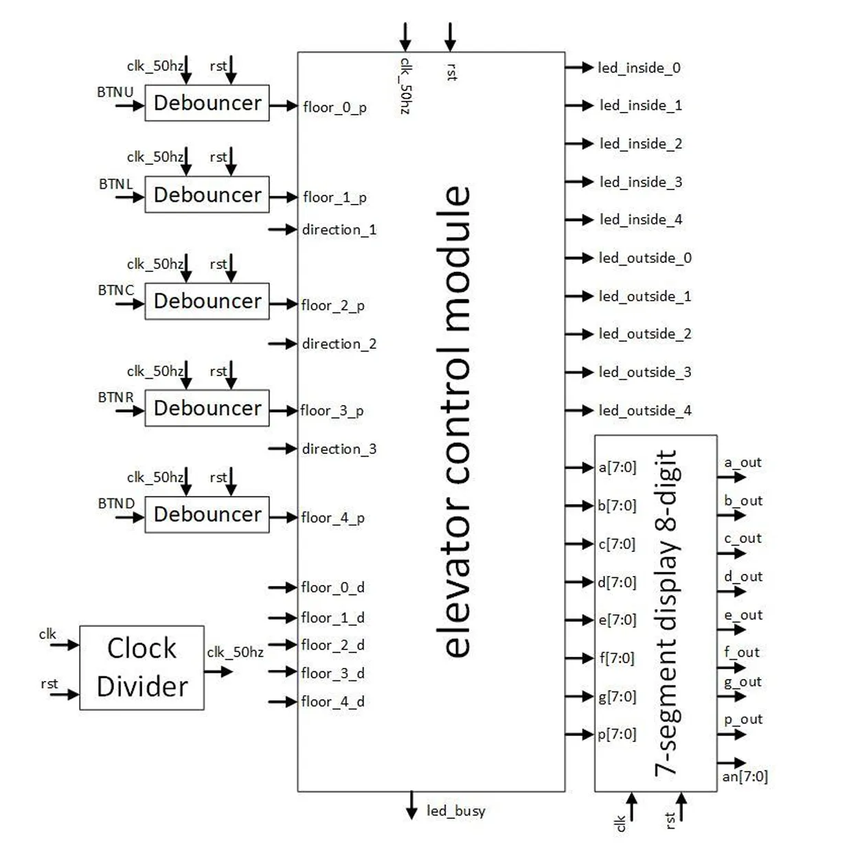
The design is built around a central elevator control module, fed and supported by several smaller modules. A clock divider takes the FPGA’s 100 MHz internal clock and brings it down to a 50 Hz (20 ms) signal, clk_50hz, slow enough to drive the control logic and to time the elevator’s behavior in human terms. That divided clock feeds both the control module and the debouncers.
Each of the five push buttons passes through its own debouncer module before reaching the control logic. A mechanical button does not produce one clean edge when pressed, it bounces, making and breaking contact many times over a few milliseconds, and without handling that, a single press would register as a burst of presses. The debouncer takes the raw button and clk_50hz and emits a single one-clock pulse per press, which the control module consumes as a clean floor_X_p input. The reset is wired to the board’s CPU Reset button, which is active-low, holding logic high until pressed, a small hardware detail that has to be accounted for in the logic.
The control module takes all of these cleaned inputs, runs the state machine that decides when to move, stop, and change direction, and produces two kinds of output: the ten LED signals, and the eight banks of cathode data (a[7:0] through p[7:0]) that encode what each digit should show. Those banks are handed to a provided eight-digit seven-segment display module, which handles the anode multiplexing and renders them as the actual --UP / FL-2 style text on the board. The displays are common-anode and active-low, so a digit is lit by driving the right cathodes to logic 0, another piece of hardware behavior the design has to respect.
Most of the difficulty lived in things that simply do not come up in software. Timing is physical: the five-second stops, the five-second floor-to-floor travel, and the busy LED are all counted in cycles of the divided clock, not delegated to a sleep call. Inputs are unreliable in a way a keyboard never is, hence the debouncers. And everything runs concurrently rather than top to bottom, so the whole thing has to be reasoned about as hardware that is all live at once, not as a sequence of instructions executing in order.
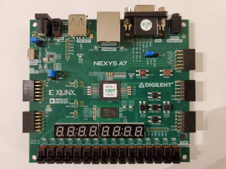
The workflow ran through Xilinx Vivado: write the Verilog, simulate the modules to verify the state machine and timing behaved before touching hardware, then synthesize the design, generate a bitstream, and program it onto the physical board through a constraint file mapping each signal to a real pin. On the board, the switches and buttons became the elevator’s controls and the displays showed it moving between floors in real time.
Takeaways
Coming from software, hardware design was a real shift. Thinking in terms of state machines, clock domains, concurrency, debouncing, and physical signal behavior was unfamiliar territory, and watching a design travel from Verilog to simulation to a board that actually responded to button presses made all of it concrete in a way reading about it never would. It was easily one of the more demanding projects I took on, and for exactly that reason one of the most instructive, a first proper look at how logic becomes hardware.